Modbus TCP/IP Overview
The Automation1 controller supports the Modbus TCP/IP Industrial Ethernet protocol. Modbus TCP/IP is an extension of the Modbus family of vendor-neutral communication protocols used for supervision and control of automation equipment. Specifically, it provides a network and transport layer in an Internet environment over the TCP/IP protocols for the Modbus application layer. The most common use of the protocol is for communication with Ethernet-based PLCs, I/O modules, and other simple field buses or I/O networks. The Modbus TCP/IP protocol is an automation standard.
The TCP/IP stack of Modbus connects over port 502, and it does not require a checksum as the lower protocol layers already provide checksum protection. The Modbus application layer data consists of the information in the table that follows.
Table: Modbus Application Layer Data
| Memory Block | Automation1 Register | Data Type | Client Access | Server Access |
|---|---|---|---|---|
| Coils | Output Bits | Boolean | Read/Write | Read-Only |
| Discrete Inputs | Input Bits | Boolean | Read-only | Read/Write |
| Holding Registers | Output Words | 16-Bit Unsigned Integer | Read/Write | Read-Only |
| Input Registers | Input Words | 16-Bit Unsigned Integer | Read-only | Read/Write |
Licensing
The Controller Plus (-CP) licensing option supports the Modbus stacks that follow on the controller:
-CP0
-
1 Modbus Server
-
1 Modbus Client
-CP1
-
1 Modbus Server
-
16 Modbus Clients
Networking
Automation1 controllers can use Modbus TCP/IP for real-time communication as a client or a server. The supporting hardware is different for drive-based and PC-based controllers.
Drive-Based Controllers
Drive-based controllers use the onboard Industrial Ethernet network interface for Modbus TCP/IP. The controller has two Industrial Ethernet ports labeled A and B. You must port A for Modbus communication. Port B does not operate for Modbus.
Tip: For drive-based controllers, use port A for Modbus communication.
PC Controllers
PC-based controllers use a dedicated PCIe network interface card (NIC) for Modbus.
IMPORTANT: Modern PC motherboards can have two NICs. Usually, one of the NICs can be used by INtime to support Industrial Ethernet communication.
Supported families of network cards:
-
Broadcom Gigabit (bge1g.rsl)
-
Intel 10/100Mbps (ie100m.rsl)
-
Intel Gigabit (ie1g.rsl)
-
RealTek 10/100 Mbps (rtl100m.rsl)
-
RealTek Gigabit (rtl1g.rsl)
See the Compatible Network Interface Cards section for individual device information.
Installation
Automation1 NICs for Modbus are passed to INtime in the same manner as the HyperWire card. After installing a standalone PCIe NIC or just utilizing a secondary, dedicated motherboard NIC, do the procedure that follows to pass the card to INtime control.
-
Open INtime Device Manager. (Start > All Programs > INtime > INtime Configuration. Then double-click INtime Device Manager).
-
In the Windows devices tree, find your network adapter. Right-click your adapter and select Pass to INtime using MSI.
-
Click File and then select Save the Configuration. The card will now be listed under the INtime devices tree.
-
Close INtime Device Manager.
IP Configuration
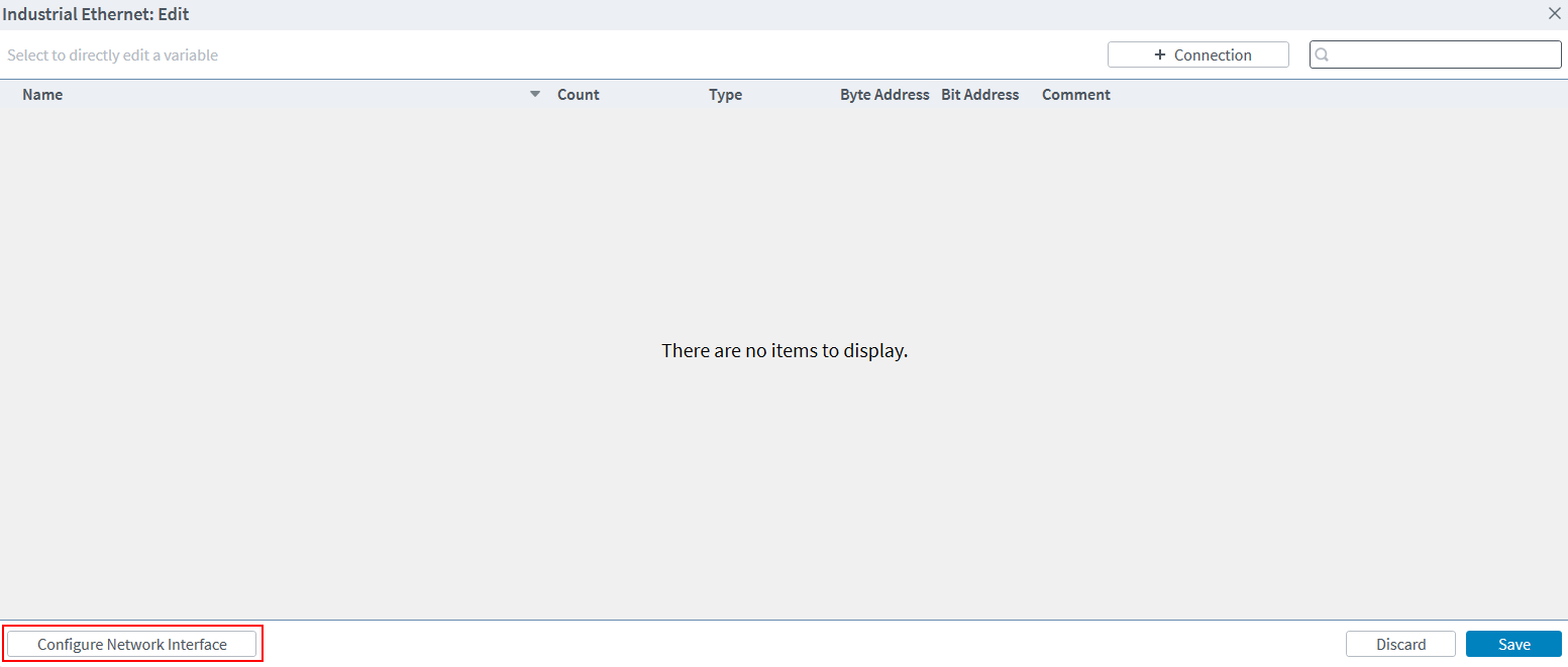
Use the Automation1 Studio to configure the applicable device driver for your network interface and to configure the IP networking information. To manage the IP networking information, click the Edit button on the Industrial Ethernet tab. For more information about this tab, see the Industrial Ethernet Tab section of the Variables & I/O module in the Develop workspace. In the Industrial Ethernet: Edit dialog, click the Configure Network Interface button in the bottom left corner.
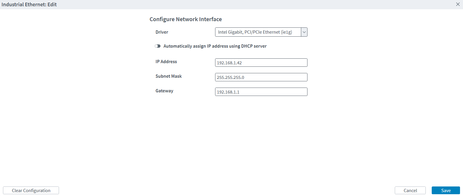
In the Configure Network Interface window, you can select the applicable driver for your NIC and enter the IP networking information. The IP Address, Subnet Mask, and Gateway are all required. To use DHCP, click the Automatically assign IP address using DHCP server toggle. To clear the NIC configuration, click the Clear Configuration button in the bottom left corner.
Create a Modbus Connection
You must create a connection to enable the Modbus Client or Server on the controller. To manage the current connections, click the Edit button on the Industrial Ethernet tab. For more information about this tab, see the Industrial Ethernet Tab section of the Variables & I/O module in the Develop workspace. In the Industrial Ethernet: Edit dialog, you can see the current connections, and you can add a new connection when you click the + Connection button. The information that you must use to create a connection is different for Modbus Client and Modbus Server.
Required Modbus Server Information
-
Name – The name of Modbus Server. This name is informational only and is used to differentiate between Modbus Server connections within Automation1.
-
ID – The Unit ID of the Modbus Server. This value is used by the Modbus protocol to differentiate between multiple Modbus Servers that are operating at the same IP address.
Required Modbus Client Information
-
Name – The name of Modbus Client. This name is informational only and is used to differentiate between Modbus Client connections within Automation1.
-
ID – The Unit ID of the Modbus Server being connected to. This value is used by the Modbus protocol to differentiate between multiple Modbus Servers that are operating at the same IP address.
-
IP Address – The IP address of the Modbus Server being connected to.
-
Port – The port of the Modbus Server being connected to.
When you configure Automation1 as a Modbus Server, the Modbus Server is configured to use port 502.
After you supply the required information, click Add to save the connection. You can now add variable mappings to the connection as described in the next section.
Configuration
Automation1 exposes the function codes of Modbus through a concept of Industrial Ethernet mappings. These Industrial Ethernet mappings let you map the memory regions of Modbus to arbitrary controller data types that you can access with the function codes. You can configure the registers that follow on the Modbus Client and Modbus Server:
Table: General Modbus Function Code Mapping
| Function Code | Modbus Variable Access |
|---|---|
|
FC 1(0x01) |
Read Output Bit |
|
FC 2 (0x02) |
Read Input Bit |
|
FC 3 (0x03) |
Read Output Word |
|
FC 4 (0x04) |
Read Input Word |
|
FC 15 (0x0F) |
Write Output Bits |
|
FC 16 (0x10) |
Write Output Words |
When you configure the controller as a Modbus Server, it will also respond to the function codes that follow:
Table: Modbus Server Function Code Mapping
| Function Code | Modbus Variable Access |
|---|---|
|
FC 5 (0x05) |
Write Output Bit |
|
FC 6 (0x06) |
Write Output Word |
|
FC 22 (0x16) |
Masked Write Output Word |
|
FC 23 (0x17) |
Read/Write Output Word |
Each Industrial Ethernet mapping supports the fields that follow:
-
Name
-
The name of the variable. This name will be automatically converted into an AeroScript variable by the controller that can be interacted with via programs or libraries.
-
-
Count
-
Determines how many contiguous sequences there will be of this variable. With counts greater than 1, the controller accesses the variables like an array. You can access the variables through an Industrial Ethernet mapping array.
-
-
Type
-
Lets you configure the Modbus registers as different data types. The data types that follow are supported.
Table: Supported Data Types
Data Type Description Bit 1-bit Boolean value UInt8 8-bit unsigned integer UInt16 16-bit unsigned integer UInt32 32-bit unsigned integer Int8 8-bit signed integer Int16 16-bit signed integer Int32 32-bit signed integer Float32 32-bit single-precision floating-point value Float64 64-bit double-precision floating-point value -
-
Byte Address
-
Configures the byte offset of the register.
-
-
Bit Address
-
Configures the bit offset of the register.
-
The final address is the sum of byteAddress * 8 + bitAddress.
-
Non-bit data types must be 8-bit byte aligned
-
-
Comment
-
Can be used to provide some information about the mapping.
-
Use Automation1 Studio to configure the Modbus mappings. For information about how to configure Industrial Ethernet mappings from the UI of the application, see the related procedures in the Industrial Ethernet Tab section of the Variables & I/O module in the Develop workspace.
Detecting a Disconnected Modbus Server
Modbus communication is always started by the Modbus Client. Thus it is not possible for the Automation1 controller to detect a disconnected Modbus Server without continuously reading or writing the variables of that server. If it is important for you to detect a disconnected Modbus Server, you must start a write or read from the Modbus Client at regular intervals. If you are not writing output mappings from the Modbus Client, you can make an input mapping (InputWord or InputBit) and regularly read from it. This will create the network traffic that is necessary so you can detect a disconnected server.
AeroScript
After you configure the mappings, the controller automatically converts the names of the Modbus variables into AeroScript properties that can be directly interacted with. The code sample that follows shows an example of the properties that would be generated from an example mapping.
| Register | Name | Count | Type | Byte Address | Bit Address |
|---|---|---|---|---|---|
| InputWords | MyInteger | 1 | UInt16 | 0 | 0 |
| OutputWords | MyReal | 4 | Float64 | 8 | 0 |
Code Sample
property $MyInteger as integer
property $MyReal[$index as integer] as real
Status Items / Data Collection
Automation1 supplies many Modbus status items that you can use directly or through Data Collection. All of the Modbus status items are in the System category. You can access the Modbus status items with the StatusGetSystemItem() function. You can add the Modbus status items to Data Collection with the DataCollectionAddSystemSignal() function.
To get status information for the client and the server configurations, use the status items that follow.
-
Modbus Client Connected
-
Modbus Client Error
-
Modbus Server Connected
-
Modbus Server Error
To access the data that is sent over the Modbus connection, use the status items that follow.
- Modbus Client Input Words
-
Modbus Client Input Bits
-
Modbus Client Input Words Status
-
Modbus Client Output Words
-
Modbus Client Output Bits
-
Modbus Client Output Words Status
-
Modbus Server Input Words
-
Modbus Server Input Bits
-
Modbus Server Output Words
-
Modbus Server Output Bits
The Modbus data status items must have one more data field to specify the connection index, data type, byte offset, and bit offset. To determine the correct additional data value, refer to the computeModbusAdditionalData() AeroScript example function that follows. If you want to use this function, you must add the code to your AeroScript program.
- $Index – The index of the connection as defined in Automation1. The first created connection is index 0. To see the currently defined connections, go to the Variables & I/O module of the Develop workspace and open the Industrial Ethernet tab. For more information about this tab, see Industrial Ethernet Tab.
- $DataType – The type of the data.
- $BitOffset – The bit offset of the data item as defined in the Modbus mapping.
- $ByteOffset – The byte offset of the data item as defined in the Modbus mapping.
function computeModbusAdditionalData($Index as integer, $DataType as ModbusRegisterDataType, $BitOffset as integer, $ByteOffset as integer) as integer
    var $additionalData as integer

    $additionalData = ($Index << 28) & 0xF0000000 | ($DataType << 23) & 0x0F800000 | ($BitOffset << 20) & 0x00700000 | ($ByteOffset & 0x000FFFFF)

    return $additionalData
end

program
	$iglobal[0] = computeModbusAdditionalData(0, ModbusRegisterDataType.Float64, 0, 256)
end
Troubleshooting
If you cannot make a connection between Automation1 and your Modbus device, try the troubleshooting steps that follow.
-
If you are using a PC controller, make sure that you selected the correct driver for your network card as listed in the Compatible Network Interface Cards section.
-
If you are using a PC controller, make sure that your network card is passed to INtime in the INtime Device Manager. See the Installation section on this page.
-
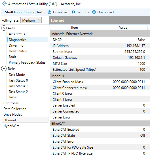
Use the Status Utility to make sure that the network information you entered is correct. The Ethernet tab shows the Industrial Ethernet Network information.
-
Use the Status Utility to make sure that a Modbus Client or Server is configured and running. The Ethernet tab shows the Modbus information.
-
If you are using a PC controller, try to ping your network card and the Modbus device you are trying to connect with through the INtime ping utility. Use the INtime RT Application Loader to run the ping.rta binary in the network7 folder.
-
You can ping the address of your network card to confirm INtime can communicate with the card.
-
You can ping the address of the Modbus device you are trying to connect with in order to confirm that the destination IP address is reachable by the Automation1 PC.
-
-
If you are unable to ping your device, confirm there is not a firewall preventing traffic between the two devices. If you are using a firewall, you will have to add an exception for the port on which you configured Modbus.
| Industrial Ethernet Network Item | Description |
|---|---|
| DHCP | Shows if the Industrial Ethernet Network is configured to use DHCP. |
| IP Address | The IP address of the Industrial Ethernet Network. |
| Subnet Mask | The Subnet Mask of the Industrial Ethernet Network. |
| Default Gateway | The Default Gateway of the Industrial Ethernet Network. |
| MAC Address | The MAC Address of the Industrial Ethernet Network adapter. |
| MTU Size | The MTU size of the Industrial Ethernet Network. |
| Estimated Link Speed (Mbps) | The estimated speed of the link layer of the Industrial Ethernet Network in Mbps. |
| Modbus Item | Description |
|---|---|
| Client Enabled Mask | Shows which Modbus Clients are configured in the Industrial Ethernet mappings |
| Client Connected Mask | Shows which Modbus Clients have an active Modbus connection |
| Client 0 Connection Error | Shows the active connection error on the first Modbus Client, if there is one |
| Client 0 Protocol Error | Shows the active protocol error on the first Modbus Client, if there is one |
| Client 1 Connection Error | Shows the active connection error on the second Modbus Client, if any |
| Client 1 Protocol Error | Shows the active protocol error on the second Modbus Client, if there is one |
| Server Enabled | Shows if the Industrial Ethernet mappings contain a Modbus Server configuration |
| Server Connected | Shows if the Modbus Server has an active Modbus connection |
| Server Connection Error | Shows the active connection error on the Modbus Server, if there is one |
Tip: If Automation1 encounters
Compatible Network Interface Cards
The NIC devices that follow are supported by INtime for use with Modbus on the PC-based Automation1 controller. Select the drop-down based on the version of INtime installed on your PC.
Select INtime 7.0.23244.1 if you originally installed Automation1 2.7 or newer on your PC.
Select INtime 6.4.19245.2 if you originally installed Automation1 2.6 or older on your PC.
| Vendor ID | Device ID | Description |
|---|---|---|
| 106b | 1645 | APPLE_DEVICE_BCM5701 |
| 10b7 | 0003 | TC_DEVICEID_3C996 |
| 1148 | 4400 | SK_DEVICEID_ALTIMA |
| 12ae | 0003 | ALTEON_DEVICEID_BCM5700 |
| 12ae | 0004 | ALTEON_DEVICEID_BCM5701 |
| 14e4 | 1600 | BCOM_DEVICEID_BCM5752 |
| 14e4 | 1601 | BCOM_DEVICEID_BCM5752M |
| 14e4 | 1644 | BCOM_DEVICEID_BCM5700 |
| 14e4 | 1645 | BCOM_DEVICEID_BCM5701 |
| 14e4 | 1646 | BCOM_DEVICEID_BCM5702 |
| 14e4 | 1647 | BCOM_DEVICEID_BCM5703 |
| 14e4 | 1648 | BCOM_DEVICEID_BCM5704C |
| 14e4 | 1649 | BCOM_DEVICEID_BCM5704S_ALT |
| 14e4 | 1653 | BCOM_DEVICEID_BCM5705 |
| 14e4 | 1654 | BCOM_DEVICEID_BCM5705K |
| 14e4 | 1658 | BCOM_DEVICEID_BCM5720 |
| 14e4 | 1659 | BCOM_DEVICEID_BCM5721 |
| 14e4 | 165a | BCOM_DEVICEID_BCM5722 |
| 14e4 | 165b | BCOM_DEVICEID_BCM5723 |
| 14e4 | 165d | BCOM_DEVICEID_BCM5705M |
| 14e4 | 165e | BCOM_DEVICEID_BCM5705M_ALT |
| 14e4 | 1668 | BCOM_DEVICEID_BCM5714C |
| 14e4 | 1669 | BCOM_DEVICEID_BCM5714S |
| 14e4 | 166a | BCOM_DEVICEID_BCM5780 |
| 14e4 | 166b | BCOM_DEVICEID_BCM5780S |
| 14e4 | 166e | BCOM_DEVICEID_BCM5705F |
| 14e4 | 1672 | BCOM_DEVICEID_BCM5754M |
| 14e4 | 1673 | BCOM_DEVICEID_BCM5755M |
| 14e4 | 1674 | BCOM_DEVICEID_BCM5756 |
| 14e4 | 1676 | BCOM_DEVICEID_BCM5750 |
| 14e4 | 1677 | BCOM_DEVICEID_BCM5751 |
| 14e4 | 1678 | BCOM_DEVICEID_BCM5715 |
| 14e4 | 1679 | BCOM_DEVICEID_BCM5715S |
| 14e4 | 167a | BCOM_DEVICEID_BCM5754 |
| 14e4 | 167b | BCOM_DEVICEID_BCM5755 |
| 14e4 | 167c | BCOM_DEVICEID_BCM5750M |
| 14e4 | 167d | BCOM_DEVICEID_BCM5751M |
| 14e4 | 167e | BCOM_DEVICEID_BCM5751F |
| 14e4 | 1680 | BCOM_DEVICEID_BCM5761E |
| 14e4 | 1681 | BCOM_DEVICEID_BCM5761 |
| 14e4 | 1684 | BCOM_DEVICEID_BCM5764 |
| 14e4 | 1688 | BCOM_DEVICEID_BCM5761S |
| 14e4 | 1689 | BCOM_DEVICEID_BCM5761SE |
| 14e4 | 168c | BCOM_DEVICEID_BCM57720 |
| 14e4 | 1690 | BCOM_DEVICEID_BCM57760 |
| 14e4 | 1692 | BCOM_DEVICEID_BCM57780 |
| 14e4 | 1693 | BCOM_DEVICEID_BCM5787M |
| 14e4 | 1694 | BCOM_DEVICEID_BCM57790 |
| 14e4 | 1696 | BCOM_DEVICEID_BCM5782 |
| 14e4 | 1698 | BCOM_DEVICEID_BCM5784 |
| 14e4 | 1699 | BCOM_DEVICEID_BCM5785 |
| 14e4 | 169a | BCOM_DEVICEID_BCM5786 |
| 14e4 | 169b | BCOM_DEVICEID_BCM5787 |
| 14e4 | 169c | BCOM_DEVICEID_BCM5788 |
| 14e4 | 169d | BCOM_DEVICEID_BCM5789 |
| 14e4 | 16a6 | BCOM_DEVICEID_BCM5702X |
| 14e4 | 16a7 | BCOM_DEVICEID_BCM5703X |
| 14e4 | 16a8 | BCOM_DEVICEID_BCM5704S |
| 14e4 | 16c6 | BCOM_DEVICEID_BCM5702_ALT |
| 14e4 | 16c7 | BCOM_DEVICEID_BCM5703_ALT |
| 14e4 | 16dd | BCOM_DEVICEID_BCM5781 |
| 14e4 | 16f7 | BCOM_DEVICEID_BCM5753 |
| 14e4 | 16fd | BCOM_DEVICEID_BCM5753M |
| 14e4 | 16fe | BCOM_DEVICEID_BCM5753F |
| 14e4 | 16ff | BCOM_DEVICEID_BCM5903M |
| 14e4 | 170d | BCOM_DEVICEID_BCM5901 |
| 14e4 | 170e | BCOM_DEVICEID_BCM5901A2 |
| 14e4 | 1712 | BCOM_DEVICEID_BCM5906 |
| 14e4 | 1713 | BCOM_DEVICEID_BCM5906M |
| 173b | 03e8 | ALTIMA_DEVICE_AC1000 |
| 173b | 03e9 | ALTIMA_DEVICE_AC1002 |
| 173b | 03ea | ALTIMA_DEVICE_AC9100 |
| Vendor ID | Device ID | Description |
|---|---|---|
| 8086 | 10b6 | 82598 |
| 8086 | 10c6 | 82598AF_DUAL_PORT |
| 8086 | 10c7 | 82598AF_SINGLE_PORT |
| 8086 | 10c8 | 82598AT |
| 8086 | 10db | 82598EB_SFP_LOM |
| 8086 | 10dd | 82598EB_CX4 |
| 8086 | 10e1 | 82598_SR_DUAL_PORT_EM |
| 8086 | 10ec | 82598_CX4_DUAL_PORT |
| 8086 | 10f1 | 82598_DA_DUAL_PORT |
| 8086 | 10f4 | 82598EB_XF_LR |
| 8086 | 10f7 | 82599_KX4 |
| 8086 | 10f8 | 82599_COMBO_BACKPLANE |
| 8086 | 10f9 | 82599_CX4 |
| 8086 | 10fb | 82599_SFP |
| 8086 | 10fc | 82599_XAUI_LOM |
| 8086 | 150b | 82598AT2 |
| 8086 | 1514 | 82599_KX4_MEZZ |
| 8086 | 151c | 82599_T3_LOM |
| 8086 | 1528 | X540T |
| 8086 | 1529 | 82599_SFP_FCOE |
| 8086 | 152a | 82599_BACKPLANE_FCOE |
| 8086 | 154a | 82599_SFP_SF_QP |
| 8086 | 154d | 82599_SFP_SF2 |
| 8086 | 1557 | 82599EN_SFP |
| 8086 | 1558 | 82599_QSFP_SF_QP |
| 8086 | 155c | X540_BYPASS |
| 8086 | 155d | 82599_BYPASS |
| 8086 | 1560 | X540T1 |
| 8086 | 1563 | X550T |
| 8086 | 15aa | X550EM_X_KX4 |
| 8086 | 15ab | X550EM_X_KR |
| 8086 | 15ac | X550EM_X_SFP |
| 8086 | 15ad | X550EM_X_10G_T |
| 8086 | 15ae | X550EM_X_1G_T |
| 8086 | 15c2 | X550EM_A_KR |
| 8086 | 15c3 | X550EM_A_KR_L |
| 8086 | 15c4 | X550EM_A_SFP_N |
| 8086 | 15c6 | X550EM_A_SGMII |
| 8086 | 15c7 | X550EM_A_SGMII_L |
| 8086 | 15c8 | X550EM_A_10G_T |
| 8086 | 15ce | X550EM_A_SFP |
| 8086 | 15d1 | X550T1 |
| 8086 | 15e4 | X550EM_A_1G_T |
| 8086 | 15e5 | X550EM_A_1G_T_L |
| Vendor ID | Device ID | Description |
|---|---|---|
| 8086 | 0438 | DH89XXCC_SGMII |
| 8086 | 043a | DH89XXCC_SERDES |
| 8086 | 043c | DH89XXCC_BACKPLANE |
| 8086 | 0440 | DH89XXCC_SFP |
| 8086 | 0d4c | PCH_CMP_I219_LM11. |
| 8086 | 0d4d | PCH_CMP_I219_V11. |
| 8086 | 0d4e | PCH_CMP_I219_LM10. |
| 8086 | 0d4f | PCH_CMP_I219_V10. |
| 8086 | 0d53 | PCH_CMP_I219_LM12. |
| 8086 | 0d55 | PCH_CMP_I219_V12. |
| 8086 | 1000 | 82542 |
| 8086 | 1001 | 82543GC_FIBER |
| 8086 | 1004 | 82543GC_COPPER |
| 8086 | 1008 | 82544EI_COPPER |
| 8086 | 1009 | 82544EI_FIBER |
| 8086 | 100c | 82544GC_COPPER |
| 8086 | 100d | 82544GC_LOM |
| 8086 | 100e | 82540EM |
| 8086 | 100f | 82545EM_COPPER |
| 8086 | 1010 | 82546EB_COPPER |
| 8086 | 1011 | 82545EM_FIBER |
| 8086 | 1012 | 82546EB_FIBER |
| 8086 | 1013 | 82541EI |
| 8086 | 1014 | 82541ER_LOM |
| 8086 | 1015 | 82540EM_LOM |
| 8086 | 1016 | 82540EP_LOM |
| 8086 | 1017 | 82540EP |
| 8086 | 1018 | 82541EI_MOBILE |
| 8086 | 1019 | 82547EI |
| 8086 | 101a | 82547EI_MOBILE |
| 8086 | 101d | 82546EB_QUAD_COPPER |
| 8086 | 101e | 82540EP_LP |
| 8086 | 1026 | 82545GM_COPPER |
| 8086 | 1027 | 82545GM_FIBER |
| 8086 | 1028 | 82545GM_SERDES |
| 8086 | 1049 | ICH8_IGP_M_AMT. |
| 8086 | 104a | ICH8_IGP_AMT. |
| 8086 | 104b | ICH8_IGP_C. |
| 8086 | 104c | ICH8_IFE. |
| 8086 | 104d | ICH8_IGP_M. |
| 8086 | 105e | 82571EB_COPPER. |
| 8086 | 105f | 82571EB_FIBER. |
| 8086 | 1060 | 82571EB_SERDES. |
| 8086 | 1075 | 82547GI |
| 8086 | 1076 | 82541GI |
| 8086 | 1077 | 82541GI_MOBILE |
| 8086 | 1078 | 82541ER |
| 8086 | 1079 | 82546GB_COPPER |
| 8086 | 107a | 82546GB_FIBER |
| 8086 | 107b | 82546GB_SERDES |
| 8086 | 107c | 82541GI_LF |
| 8086 | 107d | 82572EI_COPPER. |
| 8086 | 107e | 82572EI_FIBER. |
| 8086 | 107f | 82572EI_SERDES. |
| 8086 | 108a | 82546GB_PCIE |
| 8086 | 108b | 82573E. |
| 8086 | 108c | 82573E_IAMT. |
| 8086 | 1096 | 80003ES2LAN_COPPER_DPT. |
| 8086 | 1098 | 80003ES2LAN_SERDES_DPT. |
| 8086 | 1099 | 82546GB_QUAD_COPPER |
| 8086 | 109a | 82573L. |
| 8086 | 10a4 | 82571EB_QUAD_COPPER. |
| 8086 | 10a5 | 82571EB_QUAD_FIBER. |
| 8086 | 10a7 | 82575EB_COPPER |
| 8086 | 10a9 | 82575EB_FIBER_SERDES |
| 8086 | 10b5 | 82546GB_QUAD_COPPER_KSP3 |
| 8086 | 10b9 | 82572EI. |
| 8086 | 10ba | 80003ES2LAN_COPPER_SPT. |
| 8086 | 10bb | 80003ES2LAN_SERDES_SPT. |
| 8086 | 10bc | 82571EB_QUAD_COPPER_LP. |
| 8086 | 10bd | ICH9_IGP_AMT. |
| 8086 | 10bf | ICH9_IGP_M. |
| 8086 | 10c0 | ICH9_IFE. |
| 8086 | 10c2 | ICH9_IFE_G. |
| 8086 | 10c3 | ICH9_IFE_GT. |
| 8086 | 10c4 | ICH8_IFE_GT. |
| 8086 | 10c5 | ICH8_IFE_G. |
| 8086 | 10c9 | 82576 |
| 8086 | 10ca | 82576_VF |
| 8086 | 10cb | ICH9_IGP_M_V. |
| 8086 | 10cc | ICH10_R_BM_LM. |
| 8086 | 10cd | ICH10_R_BM_LF. |
| 8086 | 10ce | ICH10_R_BM_V. |
| 8086 | 10d3 | 82574L. |
| 8086 | 10d5 | 82571PT_QUAD_COPPER. |
| 8086 | 10d6 | 82575GB_QUAD_COPPER |
| 8086 | 10d9 | 82571EB_SERDES_DUAL. |
| 8086 | 10da | 82571EB_SERDES_QUAD. |
| 8086 | 10de | ICH10_D_BM_LM. |
| 8086 | 10df | ICH10_D_BM_LF. |
| 8086 | 10e5 | ICH9_BM. |
| 8086 | 10e6 | 82576_FIBER |
| 8086 | 10e7 | 82576_SERDES |
| 8086 | 10e8 | 82576_QUAD_COPPER |
| 8086 | 10ea | PCH_M_HV_LM. |
| 8086 | 10eb | PCH_M_HV_LC. |
| 8086 | 10ef | PCH_D_HV_DM. |
| 8086 | 10f0 | PCH_D_HV_DC. |
| 8086 | 10f5 | ICH9_IGP_M_AMT. |
| 8086 | 10f6 | 82574LA. |
| 8086 | 1501 | ICH8_82567V_3. |
| 8086 | 1502 | PCH2_LV_LM. |
| 8086 | 1503 | PCH2_LV_V. |
| 8086 | 150a | 82576_NS |
| 8086 | 150c | 82583V. |
| 8086 | 150d | 82576_SERDES_QUAD |
| 8086 | 150e | 82580_COPPER |
| 8086 | 150f | 82580_FIBER |
| 8086 | 1510 | 82580_SERDES |
| 8086 | 1511 | 82580_SGMII |
| 8086 | 1516 | 82580_COPPER_DUAL |
| 8086 | 1518 | 82576_NS_SERDES |
| 8086 | 1520 | I350_VF |
| 8086 | 1521 | I350_COPPER |
| 8086 | 1522 | I350_FIBER |
| 8086 | 1523 | I350_SERDES |
| 8086 | 1524 | I350_SGMII |
| 8086 | 1525 | ICH10_D_BM_V. |
| 8086 | 1526 | 82576_QUAD_COPPER_ET2 |
| 8086 | 1527 | 82580_QUAD_FIBER |
| 8086 | 1533 | I210_COPPER |
| 8086 | 1534 | I210_COPPER_OEM1 |
| 8086 | 1535 | I210_COPPER_IT |
| 8086 | 1536 | I210_FIBER |
| 8086 | 1537 | I210_SERDES |
| 8086 | 1538 | I210_SGMII |
| 8086 | 1539 | I211_COPPER |
| 8086 | 153a | PCH_LPT_I217_LM. |
| 8086 | 153b | PCH_LPT_I217_V. |
| 8086 | 1559 | PCH_LPTLP_I218_V. |
| 8086 | 155a | PCH_LPTLP_I218_LM. |
| 8086 | 156f | PCH_SPT_I219_LM. |
| 8086 | 1570 | PCH_SPT_I219_V. |
| 8086 | 157b | I210_COPPER_FLASHLESS |
| 8086 | 157c | I210_SERDES_FLASHLESS |
| 8086 | 15a0 | PCH_I218_LM2. |
| 8086 | 15a1 | PCH_I218_V2. |
| 8086 | 15a2 | PCH_I218_LM3. |
| 8086 | 15a3 | PCH_I218_V3. |
| 8086 | 15b7 | PCH_SPT_I219_LM2. |
| 8086 | 15b8 | PCH_SPT_I219_V2. |
| 8086 | 15b9 | PCH_LBG_I219_LM3. |
| 8086 | 15bb | PCH_CNP_I219_LM7. |
| 8086 | 15bc | PCH_CNP_I219_V7. |
| 8086 | 15bd | PCH_CNP_I219_LM6. |
| 8086 | 15be | PCH_CNP_I219_V6. |
| 8086 | 15d6 | PCH_SPT_I219_V5. |
| 8086 | 15d7 | PCH_SPT_I219_LM4. |
| 8086 | 15d8 | PCH_SPT_I219_V4. |
| 8086 | 15df | PCH_ICP_I219_LM8. |
| 8086 | 15e0 | PCH_ICP_I219_V8. |
| 8086 | 15e1 | PCH_ICP_I219_LM9. |
| 8086 | 15e2 | PCH_ICP_I219_V9. |
| 8086 | 15e3 | PCH_SPT_I219_LM5. |
| 8086 | 15f4 | PCH_TGP_I219_LM15. |
| 8086 | 15f5 | PCH_TGP_I219_V15. |
| 8086 | 15f9 | PCH_TGP_I219_LM14. |
| 8086 | 15fa | PCH_TGP_I219_V14. |
| 8086 | 15fb | PCH_TGP_I219_LM13. |
| 8086 | 15fc | PCH_TGP_I219_V13. |
| 8086 | 1a1c | PCH_ADL_I219_LM17. |
| 8086 | 1a1d | PCH_ADL_I219_V17. |
| 8086 | 1a1e | PCH_ADL_I219_LM16. |
| 8086 | 1a1f | PCH_ADL_I219_V16. |
| 8086 | 1f40 | I354_BACKPLANE_1GBPS |
| 8086 | 1f41 | I354_SGMII |
| 8086 | 1f45 | I354_BACKPLANE_2_5GBPS |
| 8086 | 294c | ICH9_IGP_C. |
| 8086 | 550a | PCH_MTP_I219_LM18. |
| 8086 | 550b | PCH_MTP_I219_V18. |
| 8086 | 550c | PCH_MTP_I219_LM19. |
| 8086 | 550d | PCH_MTP_I219_V19. |
| Vendor ID | Device ID | Description |
|---|---|---|
| 8086 | 101f | 5G_BASE_T_BC |
| 8086 | 104e | 10G_SFP |
| 8086 | 104f | 10G_B |
| 8086 | 1572 | SFP_XL710 |
| 8086 | 1580 | KX_B |
| 8086 | 1581 | KX_C |
| 8086 | 1583 | QSFP_A |
| 8086 | 1584 | QSFP_B |
| 8086 | 1585 | QSFP_C |
| 8086 | 1586 | 10G_BASE_T |
| 8086 | 1589 | 10G_BASE_T4 |
| 8086 | 158a | 25G_B |
| 8086 | 158b | 25G_SFP28 |
| 8086 | 15ff | 10G_BASE_T_BC |
| 8086 | 37ce | KX_X722 |
| 8086 | 37cf | QSFP_X722 |
| 8086 | 37d0 | SFP_X722 |
| 8086 | 37d1 | 1G_BASE_T_X722 |
| 8086 | 37d2 | 10G_BASE_T_X722 |
| 8086 | 37d3 | SFP_I_X722 |
Aerotech does not support using this network driver in Automation1.
| Vendor ID | Device ID | Description |
|---|---|---|
| 10ec | 8125 | Realtek PCIe 2.5GbE Family Controller |
| 10ec | 8136 | Realtek PCIe FE Family Controller |
| 10ec | 8161 | Realtek PCIe GbE Family Controller |
| 10ec | 8167 | Realtek PCI GbE Family Controller |
| 10ec | 8168 | Realtek PCIe GbE Family Controller |
| 10ec | 8169 | Realtek PCI GbE Family Controller |
| 1186 | 4300 | Realtek PCI GbE Family Controller |
Aerotech does not support using this network driver in Automation1.
Aerotech does not support using this network driver in Automation1.
Aerotech does not support using this network driver in Automation1.
| Vendor ID | Device ID | Description |
|---|---|---|
| 106B | 1645 | APPLE_DEVICE_BCM5701 |
| 10B7 | 0003 | TC_DEVICEID_3C996 |
| 1148 | 4400 | SK_DEVICEID_ALTIMA |
| 12AE | 0003 | ALTEON_DEVICEID_BCM5700 |
| 12AE | 0004 | ALTEON_DEVICEID_BCM5701 |
| 14E4 | 1600 | BCOM_DEVICEID_BCM5752 |
| 14E4 | 1601 | BCOM_DEVICEID_BCM5752M |
| 14E4 | 1644 | BCOM_DEVICEID_BCM5700 |
| 14E4 | 1645 | BCOM_DEVICEID_BCM5701 |
| 14E4 | 1646 | BCOM_DEVICEID_BCM5702 |
| 14E4 | 1647 | BCOM_DEVICEID_BCM5703 |
| 14E4 | 1648 | BCOM_DEVICEID_BCM5704C |
| 14E4 | 1649 | BCOM_DEVICEID_BCM5704S_ALT |
| 14E4 | 1653 | BCOM_DEVICEID_BCM5705 |
| 14E4 | 1654 | BCOM_DEVICEID_BCM5705K |
| 14E4 | 1658 | BCOM_DEVICEID_BCM5720 |
| 14E4 | 1659 | BCOM_DEVICEID_BCM5721 |
| 14E4 | 165A | BCOM_DEVICEID_BCM5722 |
| 14E4 | 165B | BCOM_DEVICEID_BCM5723 |
| 14E4 | 165D | BCOM_DEVICEID_BCM5705M |
| 14E4 | 165E | BCOM_DEVICEID_BCM5705M_ALT |
| 14E4 | 1668 | BCOM_DEVICEID_BCM5714C |
| 14E4 | 1669 | BCOM_DEVICEID_BCM5714S |
| 14E4 | 166A | BCOM_DEVICEID_BCM5780 |
| 14E4 | 166B | BCOM_DEVICEID_BCM5780S |
| 14E4 | 166E | BCOM_DEVICEID_BCM5705F |
| 14E4 | 1672 | BCOM_DEVICEID_BCM5754M |
| 14E4 | 1673 | BCOM_DEVICEID_BCM5755M |
| 14E4 | 1674 | BCOM_DEVICEID_BCM5756 |
| 14E4 | 1676 | BCOM_DEVICEID_BCM5750 |
| 14E4 | 1677 | BCOM_DEVICEID_BCM5751 |
| 14E4 | 1678 | BCOM_DEVICEID_BCM5715 |
| 14E4 | 1679 | BCOM_DEVICEID_BCM5715S |
| 14E4 | 167A | BCOM_DEVICEID_BCM5754 |
| 14E4 | 167B | BCOM_DEVICEID_BCM5755 |
| 14E4 | 167C | BCOM_DEVICEID_BCM5750M |
| 14E4 | 167D | BCOM_DEVICEID_BCM5751M |
| 14E4 | 167E | BCOM_DEVICEID_BCM5751F |
| 14E4 | 1680 | BCOM_DEVICEID_BCM5761E |
| 14E4 | 1681 | BCOM_DEVICEID_BCM5761 |
| 14E4 | 1684 | BCOM_DEVICEID_BCM5764 |
| 14E4 | 1688 | BCOM_DEVICEID_BCM5761S |
| 14E4 | 1689 | BCOM_DEVICEID_BCM5761SE |
| 14E4 | 168C | BCOM_DEVICEID_BCM57720 |
| 14E4 | 1690 | BCOM_DEVICEID_BCM57760 |
| 14E4 | 1692 | BCOM_DEVICEID_BCM57780 |
| 14E4 | 1693 | BCOM_DEVICEID_BCM5787M |
| 14E4 | 1694 | BCOM_DEVICEID_BCM57790 |
| 14E4 | 1696 | BCOM_DEVICEID_BCM5782 |
| 14E4 | 1698 | BCOM_DEVICEID_BCM5784 |
| 14E4 | 1699 | BCOM_DEVICEID_BCM5785 |
| 14E4 | 169A | BCOM_DEVICEID_BCM5786 |
| 14E4 | 169B | BCOM_DEVICEID_BCM5787 |
| 14E4 | 169C | BCOM_DEVICEID_BCM5788 |
| 14E4 | 169D | BCOM_DEVICEID_BCM5789 |
| 14E4 | 16A6 | BCOM_DEVICEID_BCM5702X |
| 14E4 | 16A7 | BCOM_DEVICEID_BCM5703X |
| 14E4 | 16A8 | BCOM_DEVICEID_BCM5704S |
| 14E4 | 16C6 | BCOM_DEVICEID_BCM5702_ALT |
| 14E4 | 16C7 | BCOM_DEVICEID_BCM5703_ALT |
| 14E4 | 16DD | BCOM_DEVICEID_BCM5781 |
| 14E4 | 16F7 | BCOM_DEVICEID_BCM5753 |
| 14E4 | 16FD | BCOM_DEVICEID_BCM5753M |
| 14E4 | 16FE | BCOM_DEVICEID_BCM5753F |
| 14E4 | 16FF | BCOM_DEVICEID_BCM5903M |
| 14E4 | 170D | BCOM_DEVICEID_BCM5901 |
| 14E4 | 170E | BCOM_DEVICEID_BCM5901A2 |
| 14E4 | 1712 | BCOM_DEVICEID_BCM5906 |
| 14E4 | 1713 | BCOM_DEVICEID_BCM5906M |
| 173B | 03E8 | ALTIMA_DEVICE_AC1000 |
| 173B | 03E9 | ALTIMA_DEVICE_AC1002 |
| 173B | 03EA | ALTIMA_DEVICE_AC9100 |
| Vendor ID | Device ID | Description |
|---|---|---|
| 8086 | 1029 | Intel 82559 PCI/CardBus Pro/100 |
| 8086 | 1030 | Intel 82559 Pro/100 Ethernet |
| 8086 | 1031 | Intel 82801CAM (ICH3) Pro/100 VE Ethernet |
| 8086 | 1032 | Intel 82801CAM (ICH3) Pro/100 VE Ethernet |
| 8086 | 1033 | Intel 82801CAM (ICH3) Pro/100 VM Ethernet |
| 8086 | 1034 | Intel 82801CAM (ICH3) Pro/100 VM Ethernet |
| 8086 | 1035 | Intel 82801CAM (ICH3) Pro/100 Ethernet |
| 8086 | 1036 | Intel 82801CAM (ICH3) Pro/100 Ethernet |
| 8086 | 1037 | Intel 82801CAM (ICH3) Pro/100 Ethernet |
| 8086 | 1038 | Intel 82801CAM (ICH3) Pro/100 VM Ethernet |
| 8086 | 1039 | Intel 82801DB (ICH4) Pro/100 VE Ethernet |
| 8086 | 103A | Intel 82801DB (ICH4) Pro/100 Ethernet |
| 8086 | 103B | Intel 82801DB (ICH4) Pro/100 VM Ethernet |
| 8086 | 103C | Intel 82801DB (ICH4) Pro/100 Ethernet |
| 8086 | 103D | Intel 82801DB (ICH4) Pro/100 VE Ethernet |
| 8086 | 103E | Intel 82801DB (ICH4) Pro/100 VM Ethernet |
| 8086 | 1050 | Intel 82801BA (D865) Pro/100 VE Ethernet |
| 8086 | 1051 | Intel 82562ET (ICH5/ICH5R) Pro/100 VE Ethernet |
| 8086 | 1059 | Intel 82551QM Pro/100 M Mobile Connection |
| 8086 | 1064 | Intel 82562EZ (ICH6) |
| 8086 | 1065 | Intel 82562ET/EZ/GT/GZ PRO/100 VE Ethernet |
| 8086 | 1068 | Intel 82801FBM (ICH6-M) Pro/100 VE Ethernet |
| 8086 | 1069 | Intel 82562EM/EX/GX Pro/100 Ethernet |
| 8086 | 1091 | Intel 82562GX Pro/100 Ethernet |
| 8086 | 1092 | Intel Pro/100 VE Network Connection |
| 8086 | 1093 | Intel Pro/100 VM Network Connection |
| 8086 | 1094 | Intel Pro/100 946GZ (ICH7) Network Connection |
| 8086 | 1209 | Intel 82559ER Embedded 10/100 Ethernet |
| 8086 | 1229 | Intel 82550 Pro/100 Ethernet |
| 8086 | 1229 | Intel 82550 Pro/100 Ethernet |
| 8086 | 1229 | Intel 82550 Pro/100 Ethernet |
| 8086 | 1229 | Intel 82551 Pro/100 Ethernet |
| 8086 | 1229 | Intel 82551 Pro/100 Ethernet |
| 8086 | 1229 | Intel 82557 Pro/100 Ethernet |
| 8086 | 1229 | Intel 82557 Pro/100 Ethernet |
| 8086 | 1229 | Intel 82557 Pro/100 Ethernet |
| 8086 | 1229 | Intel 82557/8/9 Pro/100 Ethernet |
| 8086 | 1229 | Intel 82558 Pro/100 Ethernet |
| 8086 | 1229 | Intel 82558 Pro/100 Ethernet |
| 8086 | 1229 | Intel 82559 Pro/100 Ethernet |
| 8086 | 1229 | Intel 82559 Pro/100 Ethernet |
| 8086 | 1229 | Intel 82559 Pro/100 Ethernet |
| 8086 | 1229 | Intel 82559ER Pro/100 Ethernet |
| 8086 | 2449 | Intel 82801BA/CAM (ICH2/3) Pro/100 Ethernet |
| 8086 | 27DC | Intel 82801GB (ICH7) 10/100 Ethernet |
| Vendor ID | Device ID | Description |
|---|---|---|
| 8086 | 0438 | DH89XXCC_SGMII |
| 8086 | 043A | DH89XXCC_SERDES |
| 8086 | 043C | DH89XXCC_BACKPLANE |
| 8086 | 0440 | DH89XXCC_SFP |
| 8086 | 1000 | 82542 |
| 8086 | 1001 | 82543GC_FIBER |
| 8086 | 1004 | 82543GC_COPPER |
| 8086 | 1008 | 82544EI_COPPER |
| 8086 | 1009 | 82544EI_FIBER |
| 8086 | 100C | 82544GC_COPPER |
| 8086 | 100D | 82544GC_LOM |
| 8086 | 100E | 82540EM |
| 8086 | 100F | 82545EM_COPPER |
| 8086 | 1010 | 82546EB_COPPER |
| 8086 | 1011 | 82545EM_FIBER |
| 8086 | 1012 | 82546EB_FIBER |
| 8086 | 1013 | 82541EI |
| 8086 | 1014 | 82541ER_LOM |
| 8086 | 1015 | 82540EM_LOM |
| 8086 | 1016 | 82540EP_LOM |
| 8086 | 1017 | 82540EP |
| 8086 | 1018 | 82541EI_MOBILE |
| 8086 | 1019 | 82547EI |
| 8086 | 101A | 82547EI_MOBILE |
| 8086 | 101D | 82546EB_QUAD_COPPER |
| 8086 | 101E | 82540EP_LP |
| 8086 | 1026 | 82545GM_COPPER |
| 8086 | 1027 | 82545GM_FIBER |
| 8086 | 1028 | 82545GM_SERDES |
| 8086 | 1049 | ICH8_IGP_M_AMT. |
| 8086 | 104A | ICH8_IGP_AMT. |
| 8086 | 104B | ICH8_IGP_C. |
| 8086 | 104C | ICH8_IFE. |
| 8086 | 104D | ICH8_IGP_M. |
| 8086 | 105E | 82571EB_COPPER. |
| 8086 | 105F | 82571EB_FIBER. |
| 8086 | 1060 | 82571EB_SERDES. |
| 8086 | 1075 | 82547GI |
| 8086 | 1076 | 82541GI |
| 8086 | 1077 | 82541GI_MOBILE |
| 8086 | 1078 | 82541ER |
| 8086 | 1079 | 82546GB_COPPER |
| 8086 | 107A | 82546GB_FIBER |
| 8086 | 107B | 82546GB_SERDES |
| 8086 | 107C | 82541GI_LF |
| 8086 | 107D | 82572EI_COPPER. |
| 8086 | 107E | 82572EI_FIBER. |
| 8086 | 107F | 82572EI_SERDES. |
| 8086 | 108A | 82546GB_PCIE |
| 8086 | 108B | 82573E. |
| 8086 | 108C | 82573E_IAMT. |
| 8086 | 1096 | 80003ES2LAN_COPPER_DPT. |
| 8086 | 1098 | 80003ES2LAN_SERDES_DPT. |
| 8086 | 1099 | 82546GB_QUAD_COPPER |
| 8086 | 109A | 82573L. |
| 8086 | 10A4 | 82571EB_QUAD_COPPER. |
| 8086 | 10A5 | 82571EB_QUAD_FIBER. |
| 8086 | 10A7 | 82575EB_COPPER |
| 8086 | 10A9 | 82575EB_FIBER_SERDES |
| 8086 | 10B5 | 82546GB_QUAD_COPPER_KSP3 |
| 8086 | 10B9 | 82572EI. |
| 8086 | 10BA | 80003ES2LAN_COPPER_SPT. |
| 8086 | 10BB | 80003ES2LAN_SERDES_SPT. |
| 8086 | 10BC | 82571EB_QUAD_COPPER_LP. |
| 8086 | 10BD | ICH9_IGP_AMT. |
| 8086 | 10BF | ICH9_IGP_M. |
| 8086 | 10C0 | ICH9_IFE. |
| 8086 | 10C2 | ICH9_IFE_G. |
| 8086 | 10C3 | ICH9_IFE_GT. |
| 8086 | 10C4 | ICH8_IFE_GT. |
| 8086 | 10C5 | ICH8_IFE_G. |
| 8086 | 10C9 | 82576 |
| 8086 | 10CA | 82576_VF |
| 8086 | 10CB | ICH9_IGP_M_V. |
| 8086 | 10CC | ICH10_R_BM_LM. |
| 8086 | 10CD | ICH10_R_BM_LF. |
| 8086 | 10CE | ICH10_R_BM_V. |
| 8086 | 10D3 | 82574L. |
| 8086 | 10D5 | 82571PT_QUAD_COPPER. |
| 8086 | 10D6 | 82575GB_QUAD_COPPER |
| 8086 | 10D9 | 82571EB_SERDES_DUAL. |
| 8086 | 10DA | 82571EB_SERDES_QUAD. |
| 8086 | 10DE | ICH10_D_BM_LM. |
| 8086 | 10DF | ICH10_D_BM_LF. |
| 8086 | 10E5 | ICH9_BM. |
| 8086 | 10E6 | 82576_FIBER |
| 8086 | 10E7 | 82576_SERDES |
| 8086 | 10E8 | 82576_QUAD_COPPER |
| 8086 | 10EA | PCH_M_HV_LM. |
| 8086 | 10EB | PCH_M_HV_LC. |
| 8086 | 10EF | PCH_D_HV_DM. |
| 8086 | 10F0 | PCH_D_HV_DC. |
| 8086 | 10F5 | ICH9_IGP_M_AMT. |
| 8086 | 10F6 | 82574LA. |
| 8086 | 1501 | ICH8_82567V_3. |
| 8086 | 1502 | PCH2_LV_LM. |
| 8086 | 1503 | PCH2_LV_V. |
| 8086 | 150A | 82576_NS |
| 8086 | 150C | 82583V. |
| 8086 | 150D | 82576_SERDES_QUAD |
| 8086 | 150E | 82580_COPPER |
| 8086 | 150F | 82580_FIBER |
| 8086 | 1510 | 82580_SERDES |
| 8086 | 1511 | 82580_SGMII |
| 8086 | 1516 | 82580_COPPER_DUAL |
| 8086 | 1518 | 82576_NS_SERDES |
| 8086 | 1520 | I350_VF |
| 8086 | 1521 | I350_COPPER |
| 8086 | 1522 | I350_FIBER |
| 8086 | 1523 | I350_SERDES |
| 8086 | 1524 | I350_SGMII |
| 8086 | 1525 | ICH10_D_BM_V. |
| 8086 | 1526 | 82576_QUAD_COPPER_ET2 |
| 8086 | 1527 | 82580_QUAD_FIBER |
| 8086 | 1533 | I210_COPPER |
| 8086 | 1534 | I210_COPPER_OEM1 |
| 8086 | 1535 | I210_COPPER_IT |
| 8086 | 1536 | I210_FIBER |
| 8086 | 1537 | I210_SERDES |
| 8086 | 1538 | I210_SGMII |
| 8086 | 1539 | I211_COPPER |
| 8086 | 153A | PCH_LPT_I217_LM. |
| 8086 | 153B | PCH_LPT_I217_V. |
| 8086 | 1559 | PCH_LPTLP_I218_V. |
| 8086 | 155A | PCH_LPTLP_I218_LM. |
| 8086 | 156F | PCH_SPT_I219_LM. |
| 8086 | 1570 | PCH_SPT_I219_V. |
| 8086 | 157B | I210_COPPER_FLASHLESS |
| 8086 | 157C | I210_SERDES_FLASHLESS |
| 8086 | 15A0 | PCH_I218_LM2. |
| 8086 | 15A1 | PCH_I218_V2. |
| 8086 | 15A2 | PCH_I218_LM3. |
| 8086 | 15A3 | PCH_I218_V3. |
| 8086 | 15B7 | PCH_SPT_I219_LM2. |
| 8086 | 15B8 | PCH_SPT_I219_V2. |
| 8086 | 15B9 | PCH_LBG_I219_LM3. |
| 8086 | 15BB | PCH_CNP_I219_LM7. |
| 8086 | 15BC | PCH_CNP_I219_V7. |
| 8086 | 15BD | PCH_CNP_I219_LM6. |
| 8086 | 15BE | PCH_CNP_I219_V6. |
| 8086 | 15D6 | PCH_SPT_I219_V5. |
| 8086 | 15D7 | PCH_SPT_I219_LM4. |
| 8086 | 15D8 | PCH_SPT_I219_V4. |
| 8086 | 15E3 | PCH_SPT_I219_LM5. |
| 8086 | 1F40 | I354_BACKPLANE_1GBPS |
| 8086 | 1F41 | I354_SGMII |
| 8086 | 1F45 | I354_BACKPLANE_2_5GBPS |
| 8086 | 294C | ICH9_IGP_C. |
Aerotech does not support using this network driver in Automation1.
| Vendor ID | Device ID | Description |
|---|---|---|
| 018A | 0106 | LevelOne FPC-0106TX |
| 021B | 8139 | Compaq HNE-300 |
| 10EC | 8100 | RealTek 8100 10/100BaseTX |
| 10EC | 8129 | RealTek 8129 10/100BaseTX |
| 10EC | 8138 | RealTek 8139 10/100BaseTX CardBus |
| 10EC | 8139 | RealTek 8139 10/100BaseTX |
| 1113 | 1211 | Accton MPX 5030/5038 10/100BaseTX |
| 1186 | 1300 | D-Link DFE-530TX+ 10/100BaseTX |
| 1186 | 1340 | D-Link DFE-690TXD 10/100BaseTX |
| 1259 | A117 | Corega FEther CB-TXD |
| 1259 | A11E | Corega FEtherII CB-TXD |
| 126C | 1211 | Nortel Networks 10/100BaseTX |
| 13D1 | AB06 | Edimax EP-4103DL CardBus |
| 14EA | AB06 | Planex FNW-3603-TX |
| 14EA | AB07 | Planex FNW-3800-TX |
| 1500 | 1360 | Delta Electronics 8139 10/100BaseTX |
| 1743 | 8139 | Peppercon AG ROL-F |
| 4033 | 1360 | Addtron Technology 8139 10/100BaseTX |
| Vendor ID | Device ID | Description |
|---|---|---|
| 10EC | 8136 | Realtek 8136 PCIe FE Family Controller |
| 10EC | 8161 | Realtek 8161 PCIe GBE Family Controller |
| 10EC | 8167 | Realtek 8169SC PCI GBE Family Controller |
| 10EC | 8168 | Realtek 8168 PCIe GBE Family Controller |
| 10EC | 8169 | Realtek 8169 PCI GBE Family Controller |
| 1186 | 4300 | Realtek (DLink) PCI GBE Family Controller |
Aerotech does not support using this network driver in Automation1.
Aerotech does not support using this network driver in Automation1.
Aerotech does not support using this network driver in Automation1.


